What is Extrusion? Plastic Extrusion Process

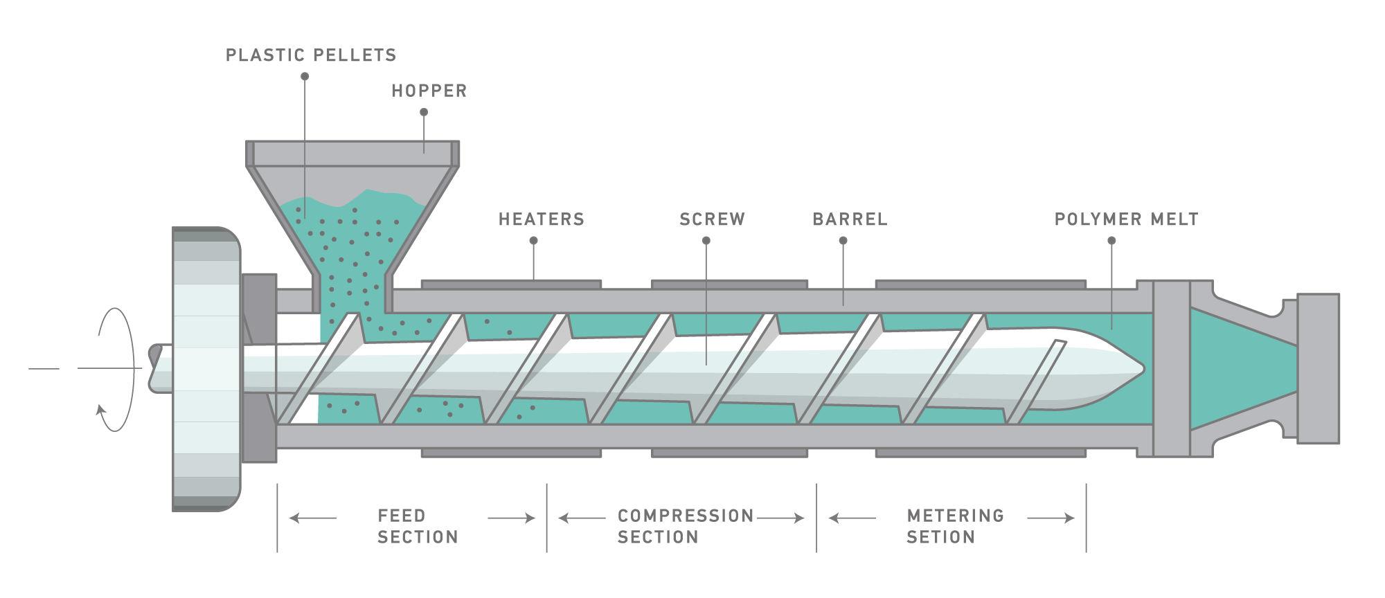
Typical Thermoplastic Extruder
The selection of the extruder barrel diameter depends on the dimensions of the profile being produced. As the throughput increases, the diameter must be increased. A length to diameter ratio (L/D) of 24:1 is recommended. If a higher capacity is needed, L/D ratios of 30:1 are preferred as they deliver a higher output capability, a more uniform output rate, and a better melt quality with the proper screw design.

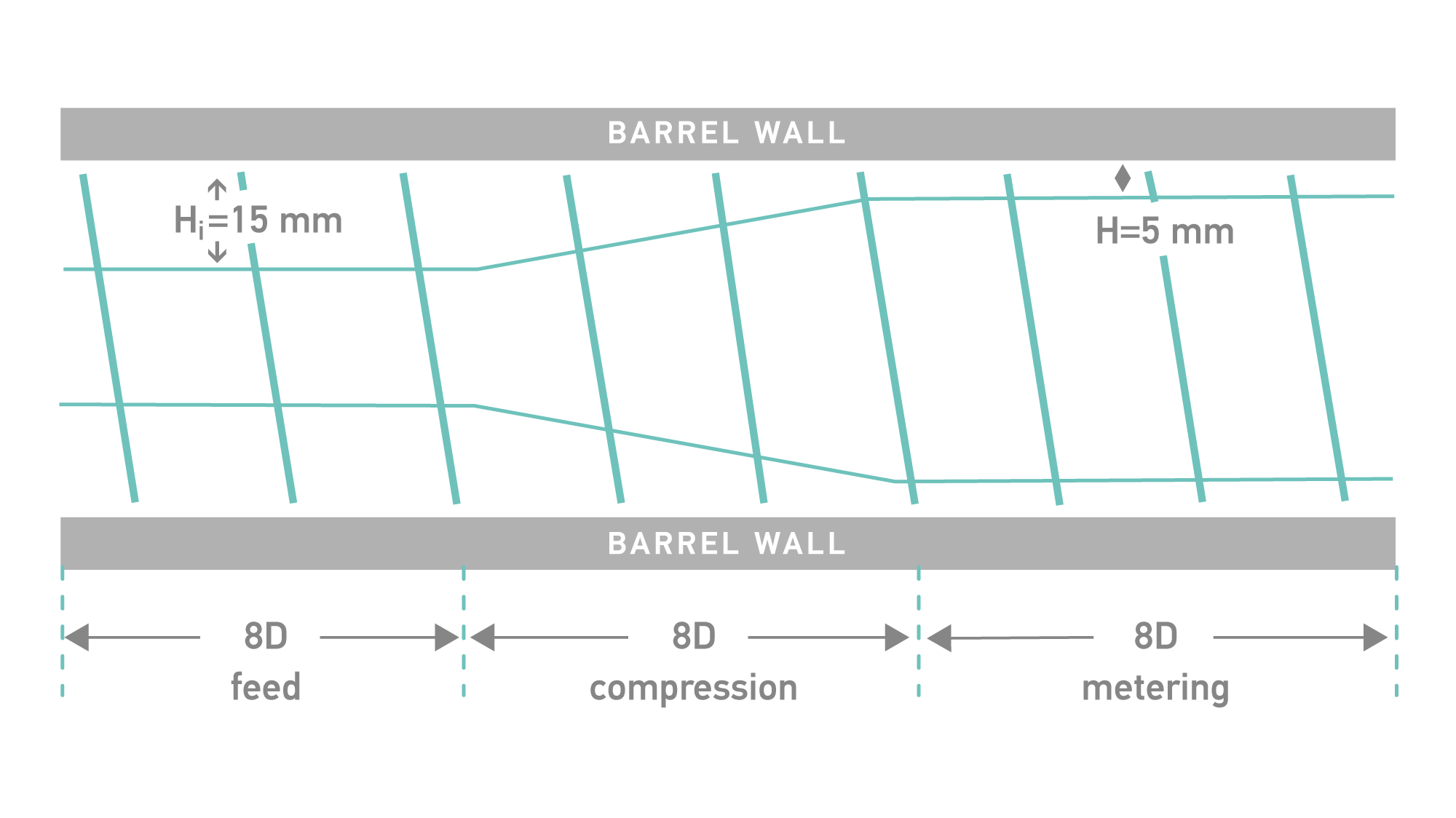
The extrusion of Elastron TPE products requires medium to high shear to plasticize properly (high shear for Elastron V products) and to ensure proper processing at the recommended temperatures. General purpose three zone screw designs (feed, transition/compression, metering) having a compression ratio of 2.5 to 3.5 with an L/D of 18:1 to 24:1 are recommended. Barrier screws, especially for Elastron V products, are used successfully and are recommended.
In order to change the melt flow from rotational to uniform laminar flow, there is a relaxation zone after the extruder barrel. During extrusion, the melt inside the barrel is compressed and stressed, and it requires uniform flow before profiling.
Extruder Screen
The breaker plate must be used for screening. Special screens must be installed on the breaker plate to catch the foreign or burned particles coming from the screw or barrel inside. Depending on the extruder size and the capacity of the breaker plates, holes from 2mm to 4mm can be used, and 20 or 40 mesh screens are recommended.
The advantages of using screens:
- Homogenize melting due to pressure
- Catch burned particles coming from the screw,
- Catch unmelted particles due to non-uniform screw design,
- Increasing shear,
- Increasing the surface quality,
- Increased back pressure for better melt quality.
Extrusion Requirements
| EXTRUSION REQUIREMENTS | |||||||||
|---|---|---|---|---|---|---|---|---|---|
| REQUIREMENTS | Elastron D | Elastron G | Elastron V | Elastron TPO | FR 6 Series | ||||
| G201 | Other | V101 | V201 | V601 | G601 | ||||
| Drying temperatures | No need | 90 ℃ | 90 ℃ 2 hours recommended |
90 ℃ | 90 ℃ | No need | 90 ℃ | 90 ℃ | |
| Drying time | 2 hours | 2 hours | 2 hours | 2 hours | 2 hours | ||||
| Screw Comp. ratio | 1.5:1 – 2.0:1 | 1.5:1 – 3.0:1 | 1.5:1 – 2.0:1 | 1.5:1 – 2.0:1 | 2.0:1 – 4.0:1 | 2.0:1 – 4.0:1 | 1.5:1 – 3.0:1 | 1.5:1 – 3.0:1 | |
| Screw L/D | 18 - 30 | 18 - 30 | 18 - 30 | 18 - 30 | 18 - 30 | 18 - 30 | 18 - 30 | 18 - 30 | |
| Feed Zone temp. | 140 - 160 | 165 - 185 | 150 - 170 | 155 - 165 | 155 - 165 | 160 - 180 | 155 - 165 | 150 - 170 | |
| Rear Zone temp. | 140 - 160 | 170 - 190 | 155 - 175 | 160 - 180 | 160 - 180 | 165 - 185 | 160 - 180 | 155 - 175 | |
| Center Zone temp. | 145 - 165 | 180 - 200 | 165 - 185 | 165 - 185 | 165 - 185 | 170 - 190 | 165 - 185 | 165 - 185 | |
| Front Zone temp. | 155 - 175 | 190 - 220 | 175 - 205 | 170 - 190 | 170 - 190 | 185 - 205 | 170 - 190 | 175 - 205 | |
| Head temp. | 155 - 185 | 195 - 225 | 180 - 210 | 180 - 210 | 180 - 210 | 190 - 220 | 180 - 210 | 180 - 210 | |
| Die temp. | 165 - 195 | 205 - 225 | 190 - 210 | 185 - 215 | 185 - 215 | 195 - 225 | 185 - 215 | 190 - 210 | |